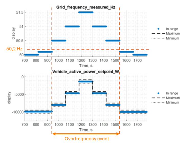
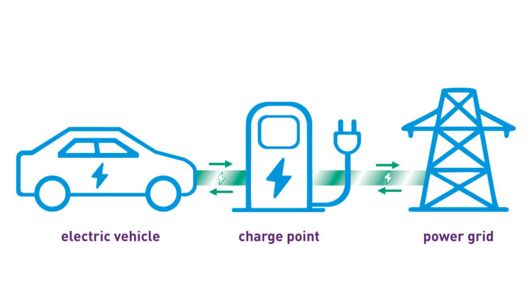
Grid code: Using Simulations for Certification
Acsystème
Diagram of general principle
Grid code and bidirectional charging
The grid code defines the conditions for access to the electricity grid for power generation systems, including how these systems should behave in the event of a grid disturbance. To be connected to the French low-voltage distribution grid, the “charging station and vehicle” system equipped with bidirectional charging must comply with the requirements specified in standard EN50549-1. The criteria for compliance with the requirements are specified by the EN50549-10 standard.
Expertise in software functions related to the grid code is essential in order to adapt functions to different grid codes (specific to each Transmission System Operator), update functions in line with changes in standards, and ensure that the system behaves in a manner that will enable it to achieve certification.
Grid code module design
Working alongside the team in charge of grid activities, the project involves starting from scratch to develop their grid code module:
- software and hardware specifications,
- architecture between charging station and vehicle,
- compliance with standards, etc.
The team’s goal is to have their own internal module for vehicle charging stations, giving vehicles a new feature: injecting electrical power from the battery directly into the distribution network, in accordance with grid codes.
Acsystème
V model – step 1 : “requirement analysis”
Typical requirement – Active power regulation based on frequency:
The system must gradually reduce the active power injected when the grid frequency exceeds 50.2 Hz.
This mechanism contributes to frequency regulation: a frequency above 50Hz indicates excess production on the grid. By automatically reducing the power injected, the system helps to restore the production/consumption balance and stabilise the grid.
Modelling the grid code
Analysis of the grid code requirements specified by EN50549-1 and regular discussions with the customer about the architecture of their system « charging station and vehicle» enabled us to identify the necessary interface changes and develop a «grid code» software module in the Simulink environment. Thanks to rigorous development and careful documention – making it possible to establish traceability between software functions, parameters, and the standard – the customer is thoroughly proficient with the content of the developed module.
Acsystème
V model – step 4 : detailed design
Acsystème
Simulink environment
A simulation of certification
In parallel with Simulink developments, analysis of the network code compliance criteria specified by EN50549-10 enabled the development of test scenarios for the software module and their validation expectations, similar to the tests performed during certification. As part of the Model-in-the-loop (MIL) approach, the use of the Acsystème validation tool AMT (Acsystème MIL toolbox) facilitated these developments while ensuring traceability between the tests and the standard. The tests were then used to validate the functions of the “grid code” module and to ensure the non-regression of functions during new development requests.
Acsystème
V model – step 8 : MIL validation
Acsystème
Simulation results on overfrequency event
Transition to the real system
The C code for the grid code module was automatically generated using the Embedded Coder toolkit, then integrated into the system’s embedded software. The software functions, linked to the EN50549 standard, were validated during the first test on a test bench. Certain functions still at the concept stage and specific to the system were also tested, and the implementation of a simulation environment driven by measurements from the real system inputs optimised reactiveness in identifying problems, proposing corrections, and validating them in simulation.
Thanks to the Model-Based Design (MBD) approach that was implemented, the code was then very quickly adapted to other country-specific grid codes from European countries and was successfully tested within a short time frame.
Future prospects
This project, which began less than a year ago with a proof of concept and a blank slate, is currently already in the industrialisation phase. There are numerous plans for future updates to provide even greater flexibility and performance:
- mass deployment of the functionality across the manufacturer’s range,
- incorporation of standards from countries outside Europe,
- continued refinement of the code architecture to achieve even greater modularity between the parts integrated directly into the vehicle or the charging station,
- new features for end customers to harness the energy available in the vehicle to power a range of equipment: V2G (grid = network; e.g., storing and reselling production), V2H (home = house, e.g., powering in the event of a power outage), V2L (load = electrical appliances, e.g., barbecue, camping refrigerator), V2B (building = building, e.g., powering a business), etc.