https://www.acsysteme.com/wp-content/uploads/2021/07/ressource-Robot-Lego-personnage-Lego.jpg

How to create algorithms with Lego®?

5,000 black and white Lego® bricks, 500 coloured marbles, 2 Lego Mindstorms bricks, 150 hours and 4 brains to create a command-control algorithm.

Some might find the Model Based Design approach specific, but it is nevertheless one of our means of initiating algorithm design projects. The explanation.

For 20 years, we have carried out many projects for our customers, and we finally have the opportunity to present you with an illustration of our expertise during our trade shows.

Indeed, this electronic, autonomous delivery device demonstrator is a perfect illustration of the model-based design (model-based design – MBD) approach used in command-control algorithm design projects. Here we worked in the Matlab/Simulink/Stateflow environment from Mathworks® and with the Lego Mindstorms platform from Lego®.

Model and algorithms

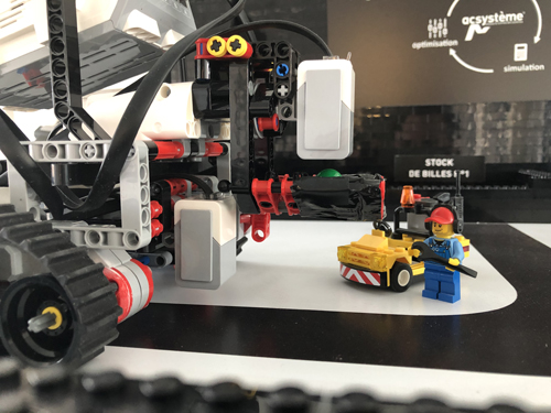
In order to highlight our expertise in modelling and designing command-control algorithms, we have developed an electric robot model with automatic guidance. This autonomous machine is responsible for delivering and sorting coloured balls from a dispenser to dedicated storage locations, whilst managing its travel autonomy depending on the capacity of its battery. (Video demonstration)

The elements of the model

This model is based physically on several elements:

  • a movement space made up of Lego® elements marking out its area of action and a line on the ground enabling the robot to locate itself,
  • an autonomous robot which recovers a ball, analyses its colour then sends it to the stock corresponding to this colour by following the black track on the ground,
  • a dispenser that randomly delivers a coloured ball each time the robot approaches it,
  • a remote control that allows a user to interact with the robot (request delivery of a coloured ball, start, stop, etc.),
  • a screen that displays in real time the information sent by the robot (colour of the ball picked up, consideration of a user request, battery status, diagnostics, etc.).

The platform for coding

With the Lego Mindstorms environment, we quickly and simply have a platform to embed our code: an EV3 programmable brick, a colour sensor, an intensity sensor, a stop sensor, a Wi-Fi transmitter/receiver, an infrared transmitter/receiver, and actuators to move the robot forwards and drive the gripper.

https://www.acsysteme.com/wp-content/uploads/2021/07/ressource-Lego-Gireg-travaille.jpg

Fig 1 : embedded code

https://www.acsysteme.com/wp-content/uploads/2021/07/ressource-Lego-Demonstrateur-Lego-complet.jpg

FIg 2 : model

https://www.acsysteme.com/wp-content/uploads/2021/07/ressource-Lego-Robot-Lego.jpg

Fig 3 : robot

The tools used

On the other side, we have our expertise in the development of control laws and Mathworks® licences to carry out our developments:

  • Matlab/Simulink: development of command-control algorithms for robot movements,
  • Stateflow: management of the robot’s state (waiting for a ball, identification of its colour, delivery, return to the dispenser, etc.),
  • AppDesigner: design of the interface to display information from the robot in real time (monitoring of ball stocks, battery level, vehicle speed, distance travelled or even diagnostic information, etc.),
  • Simulink Coder: integration of the code into the Lego® brick,
  • Matlab and Simulink Support Package for Lego Mindstorms EV3: interaction with the robot from the generated Simulink code.
https://www.acsysteme.com/wp-content/uploads/2021/07/ressource-Lego-Stateflow.png

Fig 4 : Stateflow

https://www.acsysteme.com/wp-content/uploads/2021/07/ressource-Lego-Interface-demonstrateur.png

Fig 5 : man-machine interface

Breakdown of functionalities

In a process of continuous integration, all the robot’s functionalities have been broken down into requirements and then integrated step by step into the algorithms: track following, decision-making based on colour criteria, delivery request, event detection (defect, impact, etc.), diagnostics, graphics interface, etc. For example, track following is ensured by the intensity detector located at the front of the robot. A PID regulates the intensity in front of the sensor by maintaining it at the white/black limit in a closed loop. The intersections are crossed by switching the regulation to open loop and maintaining a constant intensity at the track motors.

Techniques transposable from Lego® to your industries

This proof of concept illustrates some of Acsystème’s skills such as modelling physical systems, designing command-control, generation of embedded codes, implementation on hardware or even the development of graphics interfaces. The Lego® universe and the Matlab® environment enabled our teams to create a physical demonstrator quickly, and all the techniques used are perfectly transposable to any system to be automated.

Together, let’s give your systems intelligence!

Gireg Lanoë and Arthur Roué, March 2021.

Share this post: